Wednesday, November 27, 2019

Paramount Frame -- Installed the bar tape & checked the wheel to brake pad gap

The front brake pad to wheel rim gap is as small as I can make it without it rubbing when not applied.  The wheel is slightly out of true so there's a slight wobble when the wheel is turning.  This requires that there be a slightly larger gap from the pad to the braking surface on the rim.  The smaller the gap can be, the more responsive the brakes will feel and perform... 

The rear brake pad to wheel gap.  There's slightly less wobble on the rear wheel so the gap can be a little smaller than on the front... 

Cinelli bar tape, as installed.  I chose to leave a section of the handlebar near the gooseneck exposed. 

The bar tape was just long enough (not much extra length...). 

The fit of the brake lever hood to the bar is very good (no gaps).

The front end of the bike is basically done.  Next is the drivetrain... 


Paramount Frame -- Installed the rear brake cable and housing

Rear brake cable housing and cable, as it meeting the rear brake caliper... 


The brake cable housing goes into the adjuster (by turning the adjuster, by gripping the black rubber portion). 


They call these type of brake levers "aero" style because the cables comes out the bottom.  Previously, the cable came out of the top of the levers and looped up then down.  The cable housing is routed along the handlebar and is hidden  


The rear brake cable housing is routed through the top-tube on this frame.  This is where the housing enters...

Better picture of the integrated cable housing entry point... 

This is where the housing exits the top-tube.  It was very difficult to route the housing through the top-tube.  Had to fish the end out by very carefully twisting the housing so that the tip would be close to the exit point.  Then used a small pick tool to guide the housing out of the exit hole.  Quite a dexterity challenge! 


The cable was cut to length and a cap piece was crimped on the end of the cable to keep it from unraveling.


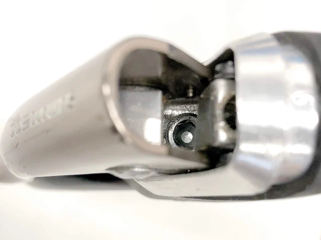
This is a view of the bottom of the brake lever where the brake cable housing sits.  The large hole on these brake levers is NOT correct.  There's supposed to be a small hole, just for the cable to go through.  It looks like someone drilled these holes out.  I can't imagine why someone would do this!  In order to make these levers work, something with a smaller center hole but with an outer size larger than this hole needs to be used.  One this lever, I found a nut that would just fit inside this space but not push through.  The hole was small enough in the middle so that the brake cable housing could sit on it.  It's what the British would call a "bodge" but it works. 

This is a picture of another pair of brake levers that shows the right configuration.  There's a round flat surface that the cable housing is supposed to rest on & a small hole just for the brake cable to go through... 

For the LH brake lever for the front brake, I found a small hollow aluminum cylinder piece I can use as an adapter.  This picture shows the adapter piece just placed in the hole where the brake cable housing is supposed to sit.  It's just large enough that it doesn't go through the hole at the bottom. 

I drilled a slightly larger hole than this piece's original inner diameter, so that the brake cable housing can sit inside this piece.  The larger hole I drilled went about 3/4 of the way through the piece so that the cable housing bottoms out in this piece.

This is the end that I drilled out.  The wall thickness is less than in the previous picture.  You can also see that the larger diameter stops about 3/4 of the way down the center.  You can see the step where the drill was stopped. 

The housing fits perfectly in the adapter. 

You can see where the cable housing stops a few mm short of the end of the adapter.

Cable housing with adapter, as it would sit when assembled to the brake lever housing.


Paramount Frame -- Installed the front brake cable and housing

The front brake cable is routed along the handlebar, like the rear.  On both sides, a few pieces of electrical tape is used to hold the brake cable housing in place, prior to installing the bar tape. 


The front brake cable housing is routed pretty directly to the front brake assembly.  There just needs to a little bit of slack to allow for movement for steering, for when the front wheel turned to the left (when turned to the right, there's actually less slack required). 


View of the full path of the front brake cable housing.

The cable was clamped to the brake with the proper adjustment for the brake shoes to wheel gap. 

The cable was cut to length and a cap was crimped on the end of the cable to keep it from unraveling.

Paramount Frame -- Installed the brake levers on the handlebar/gooseneck


The screw inside the brake lever assembly (in the middle of this picture) is the screw that tightens the clamp for the brake lever to the handlebar.  It's a large Allen head screw.

I can't remember if I can install the brake cable/housing with the brake lever mounted on the handlebar.  Will find out when I cut some new parts for the front brake...

Paramount Frame -- Received the new headset -- Installation

Bought on Amazon for about $12.  Came directly from Taiwan.  The postage is about $4.50.  No tax.


The piece on the very right (upper head tube race) goes between the two larger chrome pieces in the middle (it's out of order).

Tange is a Japanese brand & is the original manufacturer of the fork that came on the Paramount.  This new headset came from Taiwan...


The piece on the LH side (crown race) goes on the fork and the piece on the RH side (upper head tube race) goes on the top of the headtube... 


The lower headtube race was hammered (soft face) into the bottom of the headtube.  The interference fit is such that some gentle hits (many) with a soft face hammer can seat the race. Although it doesn't look like it, the race is fully seated.  There's a slight curve to the top surface so that there's a slight gap at the edge but it's seated on the inner side... 

Next is the install of the upper adjustable race (the bare headtube is ready). 


The upper headtube race is shallow and will not be visible once the upper adjustable race is installed on the fork.
The crown race has been pressed (hammered) onto the fork.  The interference fit was just right.


Fully seated.  


Just placed the upper bearing and adjustable race in place to see how it will look...  Need to grease the bearings before assembly to the fork. 


The lower bearing and seal, just placed to check the fit (OK).


The black piece below the bearing is the seal to keep dirt out...

Adjustable race, upper bearing & seal   Before applying grease

After grease (the one on the top right is the lower bearing). 

bearing seated in the upper adjustable race. 


Lower bearing placed on the fork stem.  In this picture, the bearing is upside down.  The bearing cage should point down, not up like this.  I made this mistake & assembled it.  When moving the fork, it wasn't as smooth as it should be.  I took it back apart and realized my mistake & reassembled correctly.  Afterwards, the steering feel was very smooth. 

The Upper adjustable race installed and tightened to the right amount of drag on the bearing.

The lower headtube race, bearing, seal seated on the crown race (on the fork)

The adjustable race, bearing & seal assembled to the fork & upper head tube race. 

Due to the length of the threaded portion of the fork, two washers were needed between the locknut and the adjustable race, to get the right fit to the seal on the locknut.  The other option would have been to cut the top of the fork (the threaded portion) so that it's about 3 mm shorter. 

The headset fully assembled to the frame/headtube.  The adjustable race & locknut were tightened so that there is no up/down play but the steering is still smooth and low effort. 

Installed the gooseneck (Quill stem) to the fork (with handlebar and brake levers).  The front brake cable and hosing can be installed next...